
A transformer is an essential electrical device used to transfer electrical energy between two or more circuits through electromagnetic induction. It consists of coils of wire wound around a core and operates on the principle of changing voltage levels while maintaining the same frequency. Transformers play a vital role in power distribution, allowing efficient transmission of electricity over long distances and facilitating voltage conversion for various electronic devices. They are instrumental in ensuring the reliable and safe functioning of electrical grids and a wide range of electrical appliances.
Why do you need a transformer?
Transformers are often overlooked but indispensable components of our modern electrical infrastructure. They play a crucial role in ensuring the efficient distribution of electricity and enabling various devices to function optimally. In this blog post, we will explore the reasons why transformers are essential in our daily lives and the broader electrical grid.
- Voltage Transformation: One of the primary functions of transformers is voltage transformation. Electrical energy is typically generated at power plants with a high voltage, which is necessary for efficient long-distance transmission. However, most household appliances and industrial machinery require lower voltages to operate safely. Transformers step down the voltage when electricity enters homes and businesses, ensuring that the power supplied is suitable for our devices.
- Efficient Power Transmission: Transformers enable the efficient transmission of electricity over long distances. High-voltage power lines can carry electricity over hundreds of miles with minimal energy loss. By stepping up the voltage for transmission and stepping it down at the destination, transformers make it possible to provide electricity to homes and industries located far away from power generation sources.
- Electrical Isolation: Transformers also offer electrical isolation between the primary and secondary coils. This isolation protects devices and users from electrical surges and faults. It acts as a barrier that prevents electrical disturbances from propagating between circuits, enhancing safety and preventing damage to connected equipment.
- Balancing Loads: Transformers help balance electrical loads in a grid. During peak demand periods, power needs can vary significantly. Transformers distribute electricity to where it is needed most, preventing overloading of specific parts of the grid and ensuring a stable supply of electricity to consumers.
- Compatibility with Various Devices: Transformers make it possible for a wide range of electrical devices to operate seamlessly. From the smallest household appliances to large industrial machinery, transformers ensure that each device receives the right voltage and current for its intended function.
- Renewable Energy Integration: As the world moves towards renewable energy sources like wind and solar power, transformers play a critical role in integrating these intermittent energy sources into the existing grid. They help manage fluctuations in power generation and ensure a smooth transition to a more sustainable energy future.
Transformers are the unsung heroes of the electrical world, facilitating the safe and efficient distribution of electricity to our homes, industries, and businesses. Their ability to transform voltage, balance loads, and ensure compatibility with various devices makes them indispensable in our modern lives. As we continue to evolve our energy systems to be more sustainable, transformers will remain a cornerstone of our electrical infrastructure, enabling the transition to cleaner and more efficient power generation.
Read More..
Why are transformers called stationary devices?
Transformers are often referred to as “stationary devices” due to their inherent design and operational characteristics. The primary reason for this nomenclature lies in their fixed and unchanging physical configuration during operation. Here’s why transformers are called stationary devices:
| Read Also... |
- No Moving Parts: Transformers function without any moving components. Unlike many other electrical devices, such as generators or motors, which involve rotating parts, transformers remain static while performing their crucial role in electrical systems.
- Principle of Electromagnetic Induction: Transformers operate based on the principle of electromagnetic induction, which involves the interaction of magnetic fields between coils of wire. This process does not require any mechanical motion to induce voltage or current changes.
- Consistent Operation: Transformers consistently perform their voltage transformation and power distribution functions without any physical alteration. They maintain a stable, fixed structure, whether they are stepping up or stepping down voltage levels.
- Longevity and Reliability: The absence of moving parts contributes to the longevity and reliability of transformers. Their stationary nature reduces wear and tear, making them robust and dependable devices in electrical grids and systems.
- Ease of Maintenance: Because transformers do not have moving parts, their maintenance requirements are generally simpler and less frequent compared to devices with mechanical components. Routine inspections and tests are typically sufficient to ensure their continued operation.
In summary, transformers are called “stationary devices” because they operate without any mechanical movement and maintain a fixed structure during their essential functions of voltage transformation and power distribution. This stationary nature is a key factor in their reliability and longevity, making them fundamental components of electrical infrastructure worldwide.
On what principle does the transformer work?| The Fundamental Principle Behind Transformers
Transformers are an integral part of our electrical infrastructure, playing a crucial role in power distribution and voltage transformation. To understand how they work, we must delve into the fundamental principle upon which transformers operate.
The Principle of Electromagnetic Induction: Transformers operate on the principle of electromagnetic induction, a discovery made by Michael Faraday in the early 19th century. This principle forms the foundation of transformer functionality.
Electromagnetic induction occurs when a changing magnetic field induces an electromotive force (EMF) or voltage in a nearby conductor. In the case of transformers, this process unfolds in two key components: the primary coil (also known as the input or primary winding) and the secondary coil (the output or secondary winding).
- Primary Coil: The primary coil is connected to an alternating current (AC) source. As the AC voltage alternates, it generates a continuously changing magnetic field around the coil.
- Secondary Coil: The secondary coil is placed in close proximity to the primary coil but is electrically isolated from it. The changing magnetic field produced by the primary coil induces an EMF in the secondary coil, causing a voltage to appear across its terminals.
Key Transformer Principles:
- Mutual Inductance: The phenomenon of mutual inductance is central to transformer operation. It refers to the interaction between the magnetic fields of the primary and secondary coils. When the magnetic field around the primary coil changes with the alternating current, it induces a voltage in the secondary coil due to this mutual inductance.
- Turns Ratio: Transformers are designed with a specific turns ratio, determined by the number of turns of wire in the primary and secondary coils. The turns ratio dictates how much the voltage is stepped up or stepped down. For example, if the primary coil has more turns than the secondary coil, the transformer will step down the voltage, and vice versa.
- Conservation of Energy: Transformers are highly efficient devices, with energy conservation at their core. The power (product of voltage and current) on the primary side is nearly equal to the power on the secondary side, accounting for losses due to resistance and other factors.
In essence, transformers are marvels of engineering that operate on the principle of electromagnetic induction. They harness the power of changing magnetic fields to efficiently transfer electrical energy from one coil to another, with the ability to adjust voltage levels as needed. This principle underpins their vital role in electricity distribution, enabling safe and effective power transmission across various applications and industries.
Simple structure of transformer
Its basic structure comprises a few key components, and understanding this simple structure is fundamental to appreciating how transformers work. Below, we’ll explore the primary elements of a transformer’s straightforward design:
- Core: The core is typically made of a highly magnetic material, such as laminated iron or steel. It serves as the central part of the transformer and provides a low-resistance path for the magnetic flux generated within the device. The core’s shape can vary but is often in the form of a rectangular or toroidal (donut-shaped) core, which optimizes magnetic coupling between the primary and secondary coils.
- Primary Coil (Winding): The primary coil, also known as the primary winding, is a coil of insulated copper or aluminum wire wound around one section of the core. It connects to the input voltage source, typically alternating current (AC). When AC flows through the primary coil, it generates a changing magnetic field in the core due to the coil’s winding pattern.
- Secondary Coil (Winding): The secondary coil, or secondary winding, is another coil of wire wound on a separate section of the core. It is electrically isolated from the primary coil, with no direct electrical connection. The secondary coil connects to the load or the device that requires the transformed voltage. The changing magnetic field in the core induces an electromotive force (EMF) in the secondary coil, resulting in voltage across its terminals.
- Insulation: Insulation materials are used to separate the windings of the primary and secondary coils, preventing electrical contact between them. This insulation is crucial to maintain electrical isolation and safety.
- Terminals and Leads: Each coil has terminals to connect external wires or conductors. Leads, made of insulated wire, extend from these terminals for easy connection to the electrical circuit.
The Operation:
The operation of a transformer is straightforward yet essential. When AC voltage is applied to the primary coil, it creates an alternating magnetic field in the core. This magnetic field extends to the secondary coil due to their physical proximity and the core’s magnetic properties. As a result, an EMF is induced in the secondary coil, generating voltage on the secondary side. The turns ratio between the primary and secondary coils determines whether the transformer steps up or steps down the voltage.
In summary, the simple structure of a transformer consists of a core, primary and secondary coils, insulation, and terminals/leads. Despite its uncomplicated design, this device is vital for adjusting voltage levels, enabling efficient power distribution, and ensuring the safe and reliable operation of electrical systems across various applications.
Working of transformer | How does the transformer work?
Imagine a transformer as a magic box that can change the power of electricity. It helps electricity travel safely from one place to another and makes it just the right strength for our devices.
Here’s how it works:
- Coils of Wire: Inside the transformer, there are two coils of wire, like a spring. One is called the “primary coil,” and the other is the “secondary coil.” These coils are wrapped around an iron core, which helps in the process.
- Electricity In: First, we send electricity into the primary coil. This electricity is usually strong, like the power from a power plant. When we send this strong electricity into the primary coil, it creates a magnetic field around it.
- Magic of Magnetism: This magnetic field is like a magic force. It reaches out to the secondary coil, even though they are not physically touching. It’s like a magnetic handshake!
- Electricity Out: The magic magnetic field tells the secondary coil to make electricity too. But here’s the trick: the secondary coil can make electricity that is weaker or stronger, depending on how many times it’s wrapped with wire compared to the primary coil.
- Perfect Match: So, the transformer can take strong electricity in and give us weaker electricity out, or it can take weaker electricity in and make it stronger. It’s like having a volume control for electricity.
- Safe and Useful: This is super useful because different devices, like our phones or lights, need different levels of electricity to work safely. The transformer makes sure we get the right amount of power without getting too much or too little.
In a nutshell, a transformer is like a magical helper for electricity. It uses magnetism to change the power of electricity, making it safe and perfect for all the things we use every day. That’s why transformers are so important in our electrical world!
Types Of Transformers Based On Composition
Transformers comes in various types, and one way to classify them is based on what they’re made of. In this blog post, we’ll break down the different types of transformers by their composition in simple language.
- Iron-Core Transformers: Imagine a transformer with an iron heart. Iron-core transformers are the most common type. They have a core made of laminated iron sheets. This iron core helps the transformer work better by directing the magnetic field, making it stronger. These transformers are used in many everyday devices and in our power lines for electricity distribution.
- Air-Core Transformers: Now, think of a transformer with an empty center, like a donut without the filling. Air-core transformers use air instead of iron in their core. They are not as efficient as iron-core transformers, but they’re great for special jobs where you don’t want the core to have any effect on the electrical signals. These transformers are commonly used in radio and communication equipment.
- Ferrite-Core Transformers: Ferrite-core transformers are like the transformers with a ceramic heart. They use a special ceramic material called ferrite for their core. These transformers are handy for high-frequency signals, like in your computer’s power supply or TV.
- Toroidal Transformers: Imagine a transformer shaped like a donut. Toroidal transformers have a doughnut-shaped core, usually made of iron or ferrite. They are super efficient and often found in hi-fi audio equipment because they produce less noise and electromagnetic interference.
- Oil-Immersed Transformers: Picture a transformer taking a bath in oil. Some transformers are immersed in special oils to keep them cool and insulated. These oil-immersed transformers are often used in high-power applications, like in substations, to step up or down voltages for long-distance power transmission.
- Dry-Type Transformers: Dry-type transformers are like the transformers that don’t like getting wet. They don’t use oil for cooling, making them safer for indoor use in places where oil could be a hazard, like hospitals or schools.
Transformers come in various types, each with its unique composition to suit different needs. Whether they’re made of iron, air, ferrite, or even submerged in oil, transformers are the unsung heroes of our electrical world, helping us use electricity safely and efficiently in all sorts of devices and applications.
Core Type Transformer
As Shown In The Figure, The Core Type Transformer Has Stampings L Type Of Core. The Sub Stampings Are Laminated To Each Other. At The Core Where Primary And Secondary Winding Is Done. Both Windings Are Also Insulated From Each Other. The Companion Is Also Insulated From The Core. Indings On This Core Are Done One After Another In This Way. You Can Easily Understand That The Windings In The Figure Are Shown Differently From Each Other. But In Reality The Two Indings Are On Top Of Each Other. Such Cores Have Only One Route For Flux To Flow. Because Of This, There Is Little Evidence Of Leakage Flux In It. The Average Length Of This Type Of Core Is More, But The Area Of The Hole Cut In It Is Less. Hence More Turns Have To Be Done On This Core. This Transformer Is Used For High Output Voltage.
Shell Type Transformer
As Shown In The Figure, The Core Type Of The Shell Type Transformer Has Stampings E Type And I Type. The Sub Stampings Are Laminated To Each Other. Between The Core Where Primary And Secondary Winding Is Done. Both Windings Are Also Insulated From Each Other. And This Is Done Both Indices Primary And Secondary One After The Other. While Winding On The Core, The Primary Winding Is Done First And Then The Secondary Winding On The Primary Winding. Doing So Reduces Evidence Of Leakage Flux. The Core Of This Transformer Has 2 Routes For Flux To Flow. Being Located On The Winding Beach Limb, There Is More Evidence Of Leakage Flux. The Average Length Of The Core Of A Shell Type Transformer Is Shorter, But The Area Of The Cross-Cutting Hole Is More, So Fewer Turns Have To Be Made On This Core. This Transformer Is Used For Low Output Voltage. Shell Type Transformers Are Used In Most Single Phase Transformers.
Berry Type Transformer
It Is Also Called A Distributed Core Type Transformer. As Shown In Figure. The Core Of A Berry Type Transformer Is Made Of Core Disks. A Group Is Formed By Mixing One Side Of Each Disk And Winding Is Done On That Group. The Number Of Stampings In A Berry Type Transformer Is As Much As The Flow Of Flux.
Problems With Berry Type Transformer
- The Design Of Berry Type Transformers Is A Bit Confusing.
- It Is Also A Bit Difficult To Maintain.
- Winding Is Difficult.
- Leakage Is More Critical Evidence.
This Is Why Berry Type Transformers Are Not Very Popular.
What Is The Difference Between A Core Type Transformer And A Shell Type Transformer ?
Difference Between Core Type Transformer And Shell Type Transformer
| Core Type Transformer | Shell Type Transformer |
| There Is Only One Way Of Flux Flowing. Winding Occurs On The Limb During Core Days. Due To The Winding Being Outside, The Winding From Outside Air Helps Keep The Wind Cool. The Average Length Of The Core Is Longer. The Area Of The Cross-Cutting Hole Of The Core Is Less. There Is Little Evidence Of Leakage Flux. Winding Is Easily Visible Due To Being On The Outer Limb, And Is Easy For Maintenance. It Is Suitable For High Voltage. | There Are Two Routes For Flux Flow. Winding Occurs On The Middle Limb. The Core Is Cold Because The Winding Is On The Middle Limb. The Average Length Of The Core Is Shorter. The Area Of The Cross-Cut Hole Of The Core Is More. Hence Fewer Turns Are Required. There Is More Evidence Of Leakage Flux. It Is Difficult To Repair. And Winding Is Easy. It Is Suitable For Low Voltage. |
How Many Types Of Transformers Are There According To Voltage?
There Are 2 Types Of Transformers According To More Or Less Voltage.
- Step Up Transformer
- Step Down Transformer
Step Up Transformer
The Transformer Which Gives Its Primary Winding The Output Voltage By Converting The Given Voltage To More Voltage, Is Called Step Up Transformer .
Composition Of Step Up Transformer | Composition Of Step Sub Transformer
Its Composition Is Core Type Or Shell Type. The Winding Turns Of Step Up Transformers Are More Secondary Than Primary. Because Of This, The Primary Flux Is Cut By More Secondary Turns. In Secondary Winding, More Voltage Is Produced By The Act Of Mutual Induction. Secondary Current Is Low Because The Secondary Voltage Is High. Therefore, The Primary Winding Is Of Short Turns And Thick Wire. And The Secondary Winding Is Of More Turn And Less Thick Wire. Where The Voltage Has To Be Increased, Step Up Transformer Is Used.
Step Down Transformer
The Transformer Which Gives Its Primary Winding The Output Voltage By Converting The Given Voltage To A Lower Voltage, Is Called A Step Down Transformer . The Composition Of This Transformer Is Also Core Type Or Shell Type. The Step-Down Transformer Has A Lower Primary Wire And More Turns. The Secondary Is Made Up Of Short Turns And Thick Wire. This Transformer Is Used To Reduce The Voltage.
Instrument Transformer

What Is Instrument Transformer Instrument Transformer This Is A Type Of Step Up Transformer Or Step Down Transformer . But Its Secondary Winding Is Connected To A Lower Range Voltmeter Or Ammeter. It Is Used To Measure Current And Voltage Of HT Line. Current Transformer (CT ) Is Used To Measure The Current Of HT Line And Potential Transformer (PT) To Measure Voltage .
What Is Current Transformer? (Current Transformer- CT)
What Is Current Transformer? It Is A Step Up Transformer. As Shown In Figure. The Primary Winding Of The Current Transformer Is Of Coarse Wire And Of Short Turns (One Or Two Turns Are Just One Turn In Many Places) . The Primary Winding Of The Current Transformer Is Added To The HT Line Series. Secondary Winding Is Of Fine Wire. There Are More Turns. At The End Of The Secondary Winding, A Flame Range Of Ammeter Is Attached, Which Has A Side Meaning. Ammeter Is Of Low Range Interest, But Its Scale Is Divided According To The Ratio Of The Transformer.
Working Of Current Transformer How Does A Current Transformer Work?
Working Of Current Transformer | How Does A Current Transformer Work? Due To The Current Winding Of The HT Transformer In The Series, The Current Current Flows Through The Entire Primary Winding. This Causes Fluxes To Form Around The Primary. The Flux Produced In The Primary Is Cut By The Turn Of The Secondary Indices. Due To The High Turn Of The Secondary, High Voltage Is Created In The Secondary. But The Current Of The Secondary Is Less Than The Proof Of The Ratio Of The Transformer . It Flows Through A Low Current Ammeter. The Current Flowing In Ammeter Is Really Low But The Scale Of Ammeter Is The Current Transformer Ratio Is Divided According To Because Of Which We Get Readings Of The Actual Current Flowing Through The HT Line On The Ammeter. In This Way, It Is Easier To Measure The HT Line’s High Current Than The Low Range Ammeter. Which Is Impossible Without Current Transformer. Because If The Ammeter Of Low Range Is Used At High Current Then It Will Burn. Therefore The Current Of HT Line Is Reduced Before The Current Transformer. And Then It Is Measured With A Low Range Ammeter.
Secondary Side Of Current Transformer Is Never Left Open?
Why Secondary Side Of Current Transformer Is Never Left Open? If The Secondary Winding Of The Current Transformer Is Opened Due To Any Reason, The Current Does Not Flow From The Secondary. Because Of This Fluxes Do Not Form In The Secondary. Now At This Time, Due To The Absence Of Opposing Flux To The Primary Flux, More And More Flux Flows In The Core. High Voltage Is Produced In The Secondary. Insulation Between The Core And Winding Starts To Deteriorate Due To High Voltage . The Core Of The Current Transformer Becomes Very Hot. Due To Excess Heat, The Magnetic Properties Of The Core Are Lost Forever. And Sometimes, After Some Time, There Is Also A Possibility Of Current Transformer Blast. Due To This , The Secondary Side Of The Current Transformer Is Never Left Open.. The Secondary Winding Circuit Is Always Kept Close By Adding A Low Range Ammeter To The Secondary Side. It Is Given A Side Meaning.
Why Is The Secondary Side Of The Current Transformer Earthed?
Why Is The Secondary Side Of Current Transformer Earthed? There Is Always A Possibility Of A Secondary Winding Opening Due To Some Malfunction In The Ammeter Or For Some Other Reason. Because Of This, The Deception Described Above May Be Due To Current Transformer . Therefore, Despite Adding An Ammeter To The Secondary, The Secondary Side Of The Current Transformer Is Earthed . Whenever Ammeter Is Removed From The Circuit, The Secondary Side Is Shortened. So That The Circuit Is Always Closed. So That The Current Transformer Can Avoid Possible Deception
Potential Transformer- PT
Potential Transformer: This Is A Step-Down Transformer. Secondary Winding Turns Are Thick Wire And Short Turns. This Is The Shell Type Transformer. As Shown In The Figure, The Primary Winding Of The PT Is Of More Turn To Fine Wire. The Primary Winding Of The Potential Transformer Is Parallel Pairing Of The HT Line. A Low Range Voltmeter Is Attached At The End Of The Secondary Winding. (Normally The Voltage Of The Secondary Is Stepped Down To 110 V.)
Methodology Of Potential Transformer- PT. How Does A Potential Transformer Work?
The Primary Winding Of The Potential Transformer Is Parallel To The HT Line. Primary Fluxes Are Cut By The Turns Of Secondary Windings. Secondary Turns Cause Less Voltage To Create Less Voltage In Secondary. This Is What The Voltmeter Associated With The Low Voltage Secondary Gets. In Fact The Voltmeter Gets A Low Voltage. But The Scale Of That Voltage Is Divided By The Potential Transformer Ratio . Therefore, The Reading On The Voltmeter Appears Equal To The Actual Voltage At That Time Of The HT Line. In This Way The High Voltage Of The HT Line Is Easily Measured With A Low Range Voltmeter
The following parts are attached to the three phase power Power Transformer for safety and efficiency.
An Overview of the Main Components of a Power Transformer
- Transformer Tank
- Bushing
- Tap Changer
- Conservator
- Breather
- Explosion Vent
- Buchholz Relay
- Temperature Gauge
- Transformer Radiators
- Transformer Oil
Read the brief information of all these parts below.
1) Transformer Tank
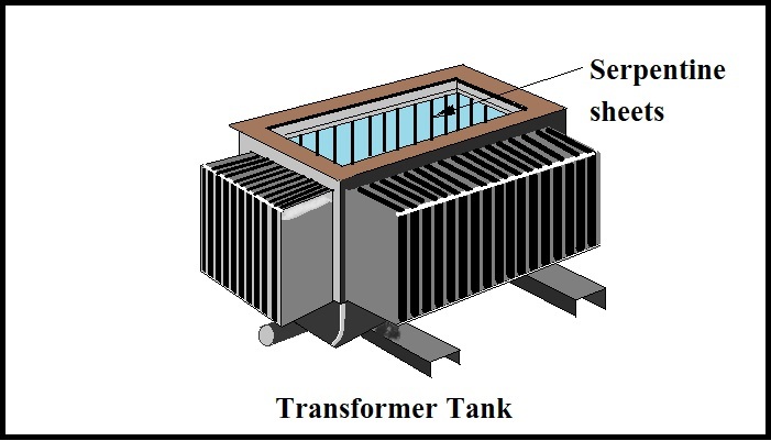
The tank of the Power Transformer is made of iron sheets. It is filled with Power Transformer oil and the Power Transformer (core and windings) is immersed in the oil.
To make the cooling system more efficient for large capacity Power Transformers, the tank of the Power Transformer is made of serpentine sheets instead of straight sheets as the use of serpentine sheets reduces the surface area of the tank. Increases and the heat emitted in the Power Transformer is emitted faster and the Power Transformer stays cool.
2) Bushing
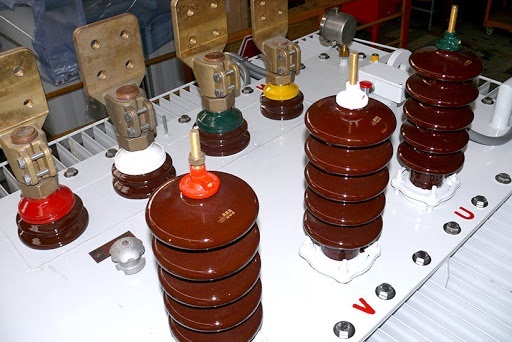
L.T. in Power Transformers. And H.T. The ends of the widings are Out from the Transformer. Bushings are fitted to supply it or to supply it. This bushing has a conductor.
Insulation is mounted on all sides around the conductor. Normally porcelain or glass is used for that insulation. Many shades of such insulation are placed around the conductor and the end of the conductor is left open.
Arrangements are made to connect the line conductors by fitting nuts at that end.
3) Tap Changer
The secondary windings of the Power Transformers are tapped for different voltages. This tapings are connected to a rotary switch. Tap switch to such a switch. It is called.
This switch is operated by hand or motor. If at some point the load on the Power Transformer increases, its output voltage decreases. In this case, the tap changer is used to stabilize the voltage by changing the tapping of the secondary with the help of the tap changer.
4) Conservator
A long circular tank is connected to the top of the Transformer tank by means of a pipe. This is called a conservator or expansion tank.
The conservator is filled with Transformer oil up to a little more than half the level. The oil level indicator is fitted to the conservator to see the oil level.
When the Transformer is working, the oil heated by the heat becomes lighter and rises and also forms gases due to that heat. The level of oil in the conservator is kept higher than expected so that there is some space to accommodate those gases.
If the oil level is maintained by filling the full conservator, there is a risk that the gas produced by the heat will increase the internal pressure and cause the tank to burst.
5) Breather
The Breather is connected to the top of the conservator by a pipe. A breather is a cylindrical pipe. Its lower end is open. It contains silica gels and calcium chloride in different chambers.
Silica gel is blue in color when completely dry. And if water is mixed in it, it turns white. While the Power Transformer is working, the oil in the Transformer tank diffuses with heat and shrinks due to cold.
So when the heat in the Transformer heats up the oil, it spreads and forms gases. These gases need to go out. And when the oil cools, the contraction of the oil creates an air cavity.
This void needs to be filled. In short, it requires breathing while the Power Transformer is working. This work is done by the Breather. Hence the Breather is called the heart of the Transformer.
When gases are formed in the tank, those gases escape from the conservator through the breather. At that time a cavity is formed in the conservator and the outside air pressure rises so the outside air enters the breather.
The silica gel and calcium chloride in the breather absorb air vapor. And the vaporless pure air fills the cavity created by the conservator.
In short, the main function of a breather is to supply vaporless and oxygen free air to the conservator. When steam is added to the oil, the dielectric of the oil decreases.
And if oxygen is mixed and sparked for some reason, oxidation takes place and oil spheres form. Such oil is not suitable for use. So another chemical is placed in the breather to absorb the oxygen in the air.
6) Explosion Vent
A curved pipe is connected to the top of the Transformer tank next to the conservator. This is called pressure release. At its front end is a thin curtain.
If at any time due to short circuit, overload or any other type of fault in the Transformer, excess heat is generated, excessive gases are produced and due to excess pressure, the curtain on the vent ruptures and all the gases escape.
So the Power Transformer is safe from explosion.
7) Buchholz Relay
This is another factor for the safety of the Transformer. This relay is connected by a pipe between the Transformer tank and the conservator.
This relay consists of two 2 balls floating on oil. Below this ball are the Mercury switches. Under normal conditions, the contacts of both switches are open. The bell circuit is connected to the upper contact.
The bell is connected to the negative end by a battery and the positive end is connected via a switch. The trip circuit is connected to the lower contact.
If the Transformer is in operation, if there is a minor defect in it, the oil heats up and the internal pressure due to the gases increases.
If the fault is of a serious nature (short circuit, overload, earth fault), the lower ball is pushed forward due to excessive internal pressure. So the trip circuit is turned on by adding contacts to its neighborhood. And disconnects from the Power Transformer supply.
this is how the relay works and protects the Transformer.
8) Temperature Gauge
The meter attached to the top of the tank to see the temperature of the Power Transformer is called the temperature gauge. This meter notifies if the temperature rises due to alarm or light.
9)Transformer Radiators
Transformer Radiators This is the main part of the power transformer. Which helps in keeping the transformer cool. The transformer radiator is connected to the transformer Tank in 2 places as shown in the figure. The radiator transformer is connected to the upper and lower end of the Transfomer Tank by piping through 2 places. Each transformer has the same number of radiators as required.
When the transformer is in service, the hot oil of the transformer tank lightens and goes upwards. This hot oil must be cooled quickly. The cooling of the heated oil is done by the radiators of the transformer. The hot oil passes through the pipe above the radiator into the radiator from where it splits into different blades of the radiator. Most of the radiator blades are exposed to outside air. Because of this, the hot oil reached in the blades of the radiator cools quickly in the blade itself. This cooled oil becomes heavier and goes downwards. This cooled oil transformer again enters the bottom of the stitch through the pipe under the radiator. This action goes on continuously. In this way the transformer is kept cool with the help of radiators.
10) Transformer Oil
It is a mineral oil. But Transformer Oil is popularly known in the market. This oil is a good type of liquid insulator. Of vaporless. Its Dielectric strength 30 to 40 kV. / mm Is. Such oil is filled in the Power Transformer tank and the winding and core are placed in it.
Keeping the Power Transformer cool and acting as an insulator between the winding and the core are two important functions of the aisle.
You should also read this
| Home Page | Click here |
| Electrical Theory | Click here |
| Earthing | Click here |
| Electrical Equipment | Click here |
| Free Electrical Training | Click here |
| Transformer | Click here |