
The Polyphase system consists of a 2 phase system or a three phase (3 phase) system (three phase system). But today, instead of single phase or 2 phase, three phase (3 phase) is produced, borne and distributed. 3 phase to single phase The advantages over phase and 2 phase are in 3 phase. The AC power supply system has more than 1 phase, that power system is called Polyphase system.
What is a three phase (3 phase) system? | Type of Polyphase system.
The AC power supply system which consists of 3 phases is called 3 phase system. In a three phase (3 phase) system, R, Y, B are three phases.
What are the advantages of 3 phase over single phase?
- The three phase (3 phase) machine has higher output as compared to the same size single phase machine.
- Three phase (3 phase) transmission is cheaper than single phase transmission for the same power. Because of this it is cheaper to transmit the three phase (3 phase) supply far and wide.
- The torque, power factor and performance of a 3 phase motor is better than a single phase motor.
- Single phase motor is not automatic. The motor of the three phase (3 phase) is automatic.
- If the changing magnetic field is created by single phase, then the magnetic field rotating from the three phase (3 phase) is formed.
- In a 3 phase system, 2 types of voltage are found in phase voltage and line voltage (eg 220 volts, 415 volts), then only phase voltage (220 volts) is found to be the same voltage in a single phase.
- The power factor is good in a three phase (3 phase) system. Hence current is less cost in three phase (3 phase) compared to single phase for same power.
- Three phase (3 phase) has lower I2 × R power loss and I × R voltage drop than single phase.
- The 3 Phase motor is made of more horsepower (HP).
- Three phase (3 phase) alternator synchronization is easy to do.
How is 3 phase produced?
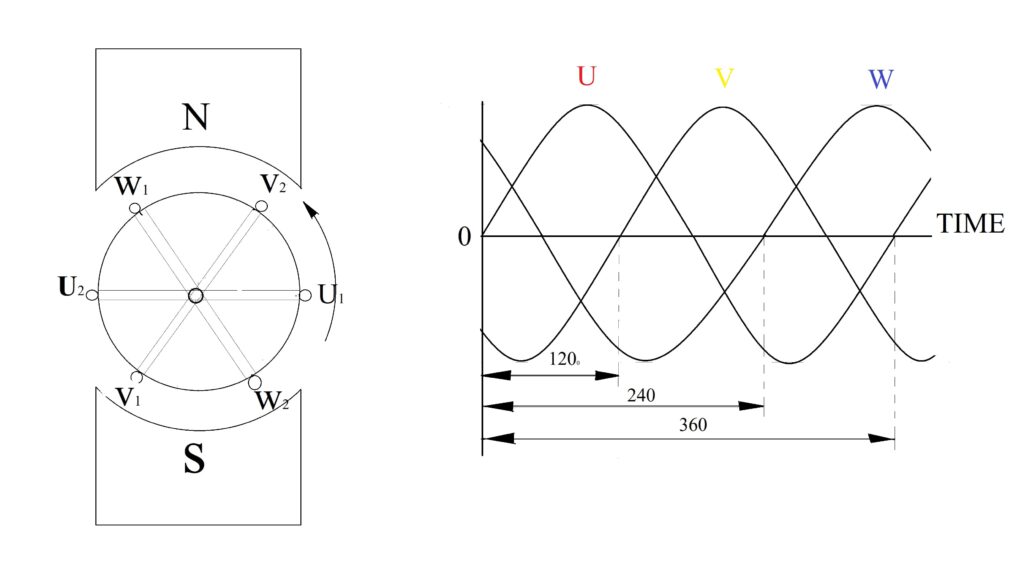
In a Uniform Electrical Magnaetic Field, 3 conductors are rotated at a distance of 120 ° from each other. In those three conductors, EMF (Electro Motive Force) is formed according to the element of Electro Magnetic Induction of Michael Faraday . According to this element, 3 phase is produced. Look at the figure above. The three conductors U, V and W are placed between them 120 ° electrically. Those anti-clockwise are rotated in a uniform magnetic field between the pole ‘N’ ‘S’ of the stationary magnet. The U1 conductor goes from bottom to top, while at the same time the V2 conductor also goes from bottom to top. And at the same time the W1 conductor moves from top to bottom. If we consider only this moment in the figure, then U is parallel to the conductor magnetic lines, due to which U conductor will not cut the magnetic lines. And in this moment there will not be any EMF in it. At this very moment, the V2 conductor cuts the magnetic lines in a little proof, due to which EMF is formed in it. According to Fleming’s right hand rule, if the direction of that EMF to be produced in V2 is known, the direction of that EMF will be negative according to figure. Because of the W1 conductor coming down from the top, the direction of the EMF produced in that conductor will be positive. This means that out of the three phases formed at any given moment in a round of three conductors, one phase is positive, the other negative and the third phase is around zero or zero. In this way, three phase (3 phase) is formed.
- In this, the algebraic sum of the EMF of the three phases to be constructed is zero ‘0’.
- The frequency of the three phases is the same.
- The phase difference between the three phases is 120 °.
Phase Sequence
In a 3 phase formation, the order of the three phases moving up to their respective pick values is the phase sequence. Or The order in which the three phases reach their maximum value or at least the value is known as phase sequence. Examples Understand that initially U reaches its pick value, after that V reaches its pick value and finally W reaches its pick value, then their phase sequence will be U, V, W in this way. It is worth noting that the winding of the three phase (3 phase) alternator or the winding of the three phase (3 phase) motor is represented by U, V, W. Phase sequences of 6 terminals of three windings U1 U2, V1 V2, and W1 W2 are represented by these letters. And the phase or line is represented by these letters L1, L2, L3.
Some words and their definitions in the context of three phase (3 phase)
Phase voltage
The voltage found in any one phase and neutral terminal from 3 phase is called phase voltage. It is always represented by the letter Vph.
Line Voltage
The voltage found in any of the 2 phases of the 3 Phase is called the Line voltage. It is represented by VL . It is also called Phase to Phase Voltage.
Phase current
The current flowing through a phase winding is called phase current. It is denoted by the letter Iph.
Line current
The current flowing through any two phase windings in the three phase (3 phase) is called line current. Let us denote it with IL.
Balanced load
In a three phase (3 phase) supply system, the phase or line current of the load connected at all the three phases, power and power factor are the same. So that load is called balance load.
Unbalanced load
In a 3 Phase supply system, the phase or line current, power and power factor of the connected load at all three phases are different. So that load is called unbalance load.
Phase power
The power measured in any one phase and neutral in 3 phase is called phase power. And the power measured in all three phases is called total power.
You should also read this
| Home Page | Click here |
| Electrical Theory | Click here |
| Earthing | Click here |
| Electrical Equipment | Click here |
| Free Electrical Training | Click here |
| Transformer | Click here |